 |
Ryan McLaughlin | Mechatronics Portfolio
|


|
|
Ryan McLaughlin | Mechatronics Portfolio
|
|
In week 2, with serial communication mostly figured out, it was time to add in hardware.
The first component to our system were encoders. More specifically, our developement board has two E4T optical encoders, one for each motor (see Week 3: Interfacing with DC Motors and Implemenation of a Controller for more detail on motors). Although the code developed in week 2 was straightforward, major difficulties arose due to hardware issues. For reasons never fully understood, the encoders we were using would at times cap out at a certain value, and would sporatically work again. These issues continued somewhat into the coming weeks, but again for reasons unknown, the encoders seemed to function more consistently in the follwoing weeks when being run simultaneously with a controller task.
Before adding in powered motors, we began with understanding how to read and correctly update the position of our encoders. The main tasks to be completed in week 2 were: setting up the encoders on the correct timer channels, and implementing an algorithm to translate changes in timer counts into angular displacement values for the encoders. This algorithm is needed because while encoder angle in either the positive or negative direction is unbounded, the encoder count has a limit of 65535 ticks.
In addition to this algrorithm, methods for retrieving the current position, current delta value (difference between the last two positions), and current speed were all added to the encoder driver. These would not only be called on by certain commands from the PC (when the user presses a given keyboard key), but these methods would be used by the controller task developed in weeks 3 and 4. For full documentation of the encoder driver class, see encoder.encoder. See below for the state transition diagram for the encoder task (later replaced by a more complete controller task, see Controller Task).
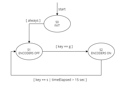
Although we could run the encoder driver itself directly in a main file, the best way to seperate a driver class from the corresponding task is to create a new file. As this file was absorbed into a larger controller task file (see controllerTask.py), the source code for the encoder task only is not available, but the main premise was to run methods from the encoder drivers periodically. With this task setup, we can easily create multiple objects of encoders. For a task diagram from week 2, see Figure F.4 below, and for the final task diagram, see Final Task Diagram.
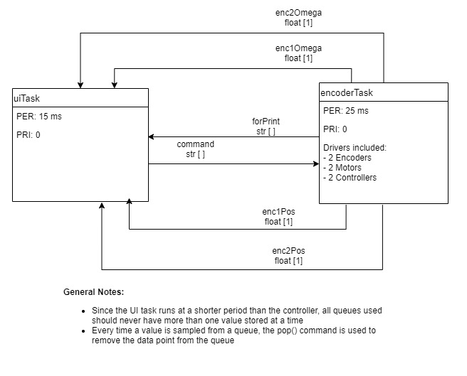
In addition to drivers and a task for the encoders, we now needed a method for sharing data between files on the Nucleo. The most efficient way of sharing data between files is to used a shared file, which all files on the board have access to. For example, if a PC command (key press) is sent to the Nucleo, the UI Task can add a new command to a queue in the shared file (see shares.py). This command can then be read by the encoder or controller task, causing some action. Using this sequence of events, the PC and all files on the Nucleo can interact with each other, instead of having to recreate data in multiple places.
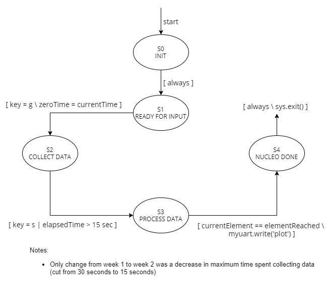
Lastly, the UI task finite state machine underwent some small changes from week 1 to week 2. With encoders gathering data (and more of it than before with just a function), we only wanted to collect data for a maximum of 15 seconds. The state transition diagram shown below for the UI task was not altered in any significant way after week 2.
Click here to advance to Week 3: Interfacing with DC Motors and Implemenation of a Controller.